USB-Mux Overview
Theory Of Operation
USB paths inside the USB-Mux
In this chapter DUT describes the Embedded Device under Test. The host is the computer controlling the operation of the USB-Mux. The device is a USB device connected to the device port, eg. a flash drive.
The USB-Mux contains a 3 port USB hub:
The microcontroller inside the USB-Mux is connected to port 1.
The DUT can be multiplexed to port 2.
The device can be multiplexed to port 3.
The USB-Mux can be instructed in software to create the following conditions:
Isolation of the DUT and Device ports. This is the default mode after power on.
                                     +-----------------------+
                                     | USB-Mux               |
                                  +--|                       |
                                  |  | SN:   00002           |
                                  |  | Path: 5-1.3.4.2.1     |
                                  |  +-----------------------+
       VCC: 4.99V    +---------+  |
Host |>--------------|       1 |--+         ID: High
                     |         |           VCC: 0.00V
                     |       2 |----x    ------------|> DUT
                     |         |
                     |       3 |----x    ------------|> Device
                     +---------+           VCC: 0.00V
A direct connection between the DUT, in the USB Host role, to the Device port of the USB-Mux.
                                     +-----------------------+
                                     | USB-Mux               |
                                  +--|                       |
                                  |  | SN:   00002           |
                                  |  | Path: 5-1.3.4.2.1     |
                                  |  +-----------------------+
       VCC: 4.99V    +---------+  |
Host |>--------------|       1 |--+         ID: Low
                     |         |           VCC: 5.12V
                     |       2 |----x    +-----------|> DUT
                     |         |         |
                     |       3 |----x    +-----------|> Device
                     +---------+           VCC: 5.11V
A connection via the USB-Hub integrated in the USB-Mux between the DUT, in the USB Device role, and the test host.
                                     +-----------------------+
                                     | USB-Mux               |
                                  +--|                       |
                                  |  | SN:   00002           |
                                  |  | Path: 5-1.3.4.2.1     |
                                  |  +-----------------------+
       VCC: 4.99V    +---------+  |
Host |>--------------|       1 |--+         ID: High
                     |         |           VCC: 4.79V
                     |       2 |---------------------|> DUT
                     |         |
                     |       3 |----x    ------------|> Device
                     +---------+           VCC: 0.00V
A connection via the USB-Hub integrated in the USB-Mux between the Device port and the host.
                                     +-----------------------+
                                     | USB-Mux               |
                                  +--|                       |
                                  |  | SN:   00002           |
                                  |  | Path: 5-1.3.4.2.1     |
                                  |  +-----------------------+
       VCC: 4.99V    +---------+  |
Host |>--------------|       1 |--+         ID: High
                     |         |           VCC: 0.15V
                     |       2 |----x    ------------|> DUT
                     |         |
                     |       3 |---------------------|> Device
                     +---------+           VCC: 4.79V
Modes 3 and 4 can be combined to connect both DUT and device to the host.
                                     +-----------------------+
                                     | USB-Mux               |
                                  +--|                       |
                                  |  | SN:   00002           |
                                  |  | Path: 5-1.3.4.2.1     |
                                  |  +-----------------------+
       VCC: 4.99V    +---------+  |
Host |>--------------|       1 |--+         ID: High
                     |         |           VCC: 4.80V
                     |       2 |---------------------|> DUT
                     |         |
                     |       3 |---------------------|> Device
                     +---------+           VCC: 4.80V
Switch sequence when multiplexing
When the USB-Mux switches between modes using the control software the following steps are executed:
The currently active connection is electrically disconnected.
The control software waits 0.5s for the switches to settle and for the bus-members to notice a disconnect.
The new connection is made.
The new connection is discovered by the bus-members via USB hotplug logic.
Using the ID pin
The USB-Mux has an ID pin output in the DUT connection. By default this pin is switched according to the connection made to the DUT. This behavior can be disabled.
The ID pin is used to signal the following modes to a DUT:
When the ID pin is pulled low a OTG-capable DUT will go into the host mode.
When the ID pin is floating (usually high) the DUT will go into device mode.
Hardware
The following figure shows a rendering of the USB-Mux, including the connectors and their associated case-printing:
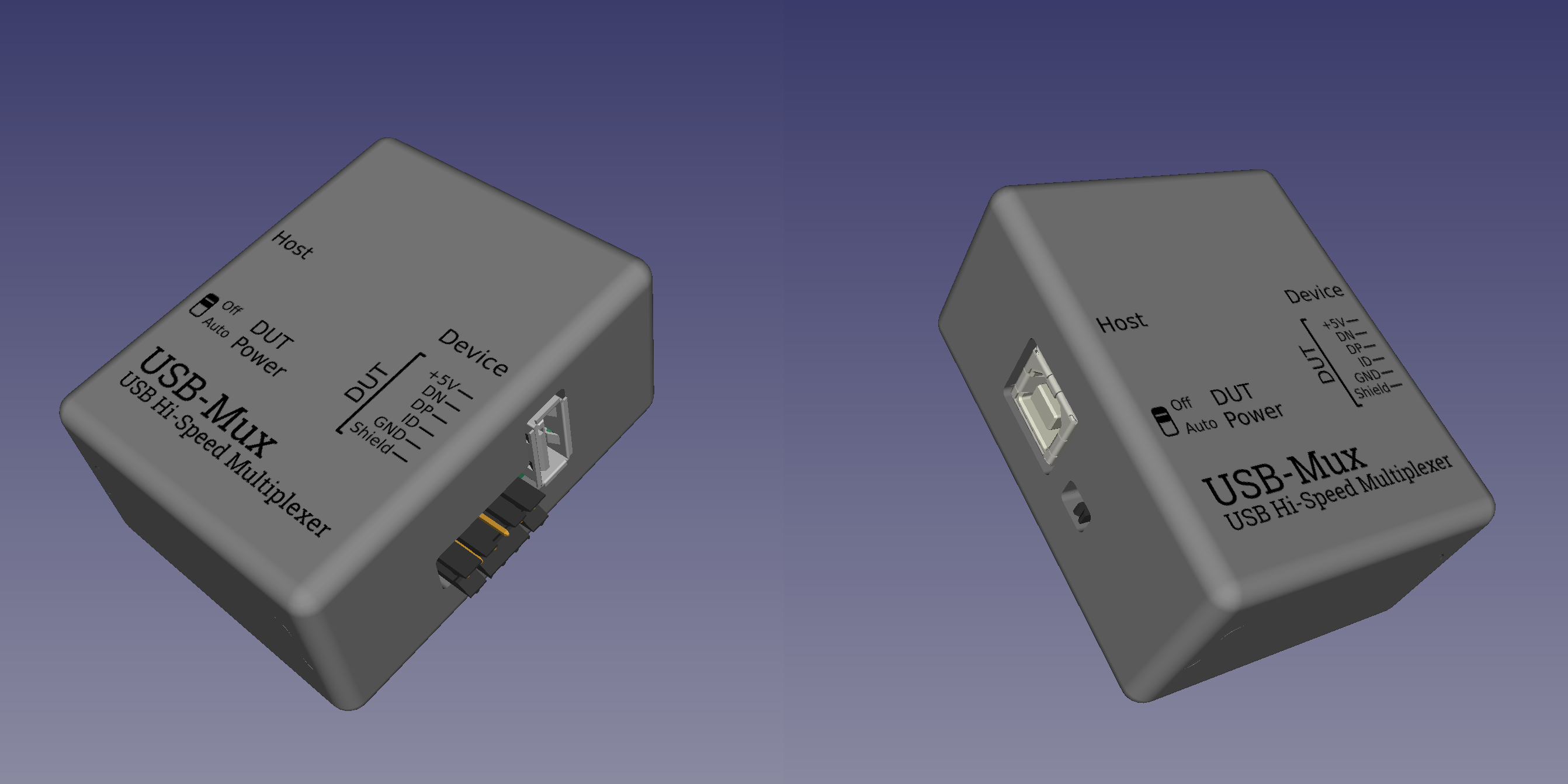
The connectors and their respective function are:
On the right side of the device:
Device: USB port that can either be connected through to the DUT or Host.
DUT: USB signals on a Pin-Header to connect to the DUT via appropriate cabling. Can be connected to the Device or Host port using the control software.
On the left side of the device: