
LXA IOBus
With a large number of embedded devices in a remote lab infrastructure , USB regularly proves unreliable: Embedded devices cannot be reached or they show strange error patterns that are hard to reproduce, leading to developer frustration. To minimize developer frustration we have developed the LXA IOBus line of products, that are based on the very reliable CAN protocol. IOBus is inspired by the CANOpen standard and allows hot-plugging and automatic discovery of devices.
One of our focuses for the design of our software and hardware is the integration of labgrid. The LXA IOBus is directly usable as a tool for automated tests of embedded devices and helps to improve embedded software quality.
LXA IOBus Server
The LXA IOBus Server is an interface between the devices on the IOBus and the developer. It provides an intuitive Web-interface, as well as an easy to use REST based API.
Resources
| Software: | https://github.com/linux-automation/lxa-iobus |
| Manual: | https://lxa-iobus.readthedocs.io/en/latest/ |
LXA IOBus 4DO-3DI-3AI

The LXA IOBus 4DO-3DI-3AI extends an IOBus network by four digital outputs, three digital inputs and three analog inputs.
The digital outputs are implemented using solid state relais and allow the galvanically isolated switching of very small loads. Exemplary use cases are the simulation of button presses or the setting/resetting of jumper connections to trigger a system reset or select boot modes.
The digital inputs are also implemented using solid state relais and can for example be used to provide binary feedback to your test automation system to determine if a test was successful.
The analog inputs are non-isolated and may for example be used to monitor supply voltages. This can for example be used to ensure that the system has returned to a known good state after the previous test run.
Minimal Setup
For a minimal IOBus setup you will need:
- A Linux-based system to run the iobus-server.
- A CAN adapter that lets said system talk the CAN protocol. We like the open-hardware candleLight USB-CAN adapter.
- A 120Ω resistor to terminate the CAN-bus.
- A 12V power supply.
- 9-wire ribbon cable.
- Male and female D-Sub 9 connectors to crimp onto the ribbon cable
- A female D-Sub 9 connectors to solder the power supply leads and termination resistor to.
- A bit of patience to follow the hardware preparation instructions described in our manual .
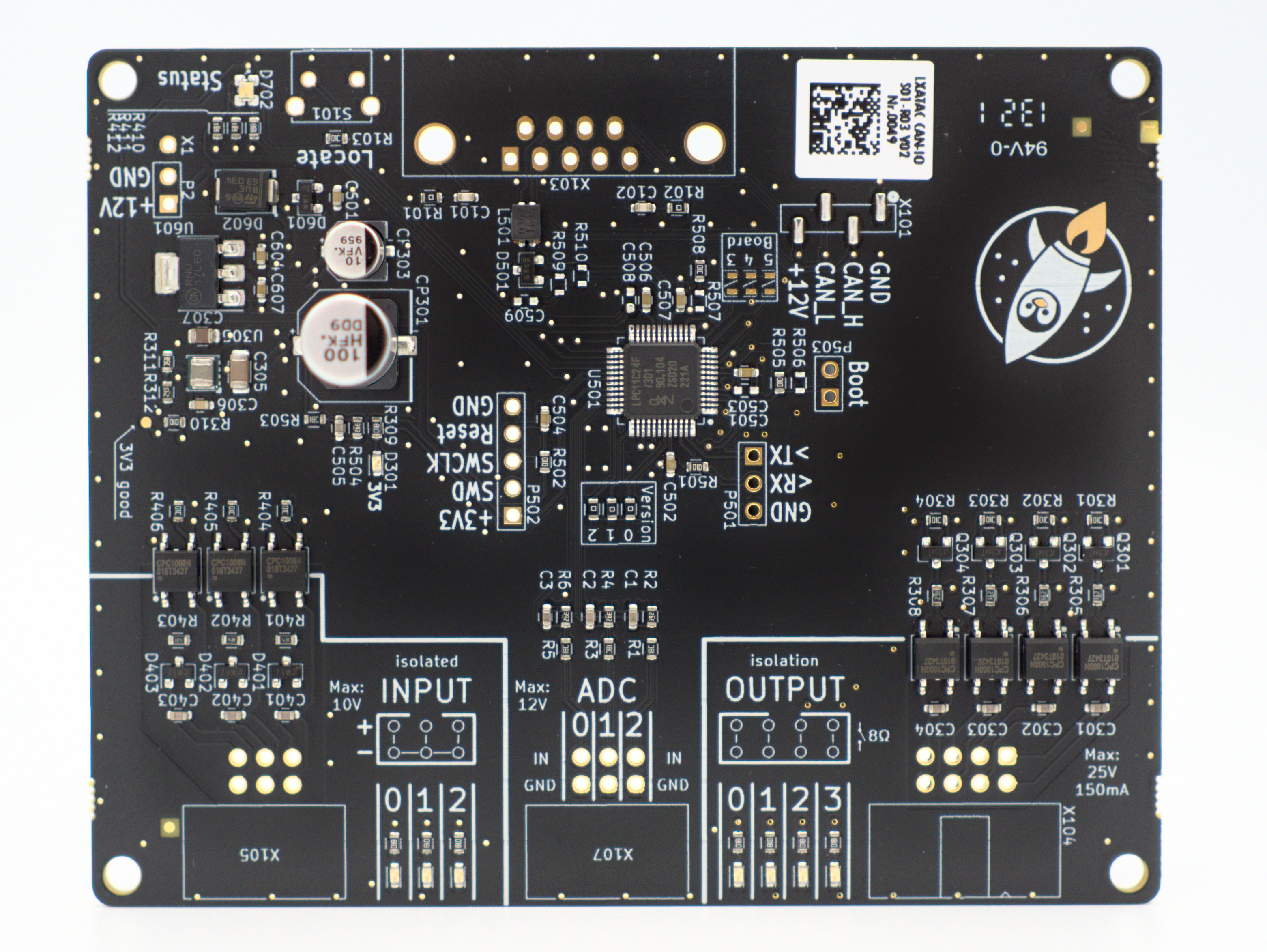
LXA IOBus 4DO-DI-3AI circuit board
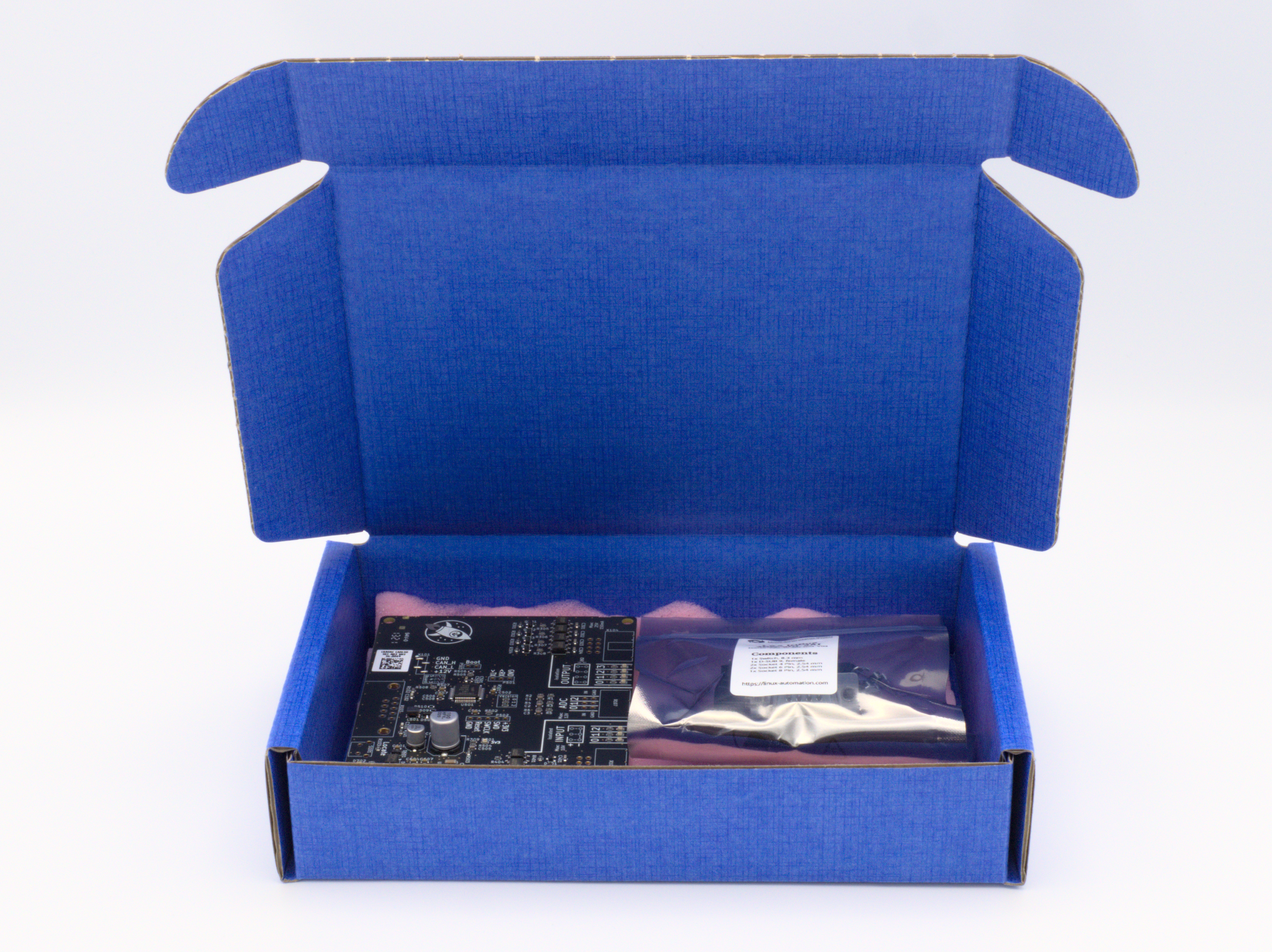
LXA IOBus 4DO-3DI-3AI in packaging
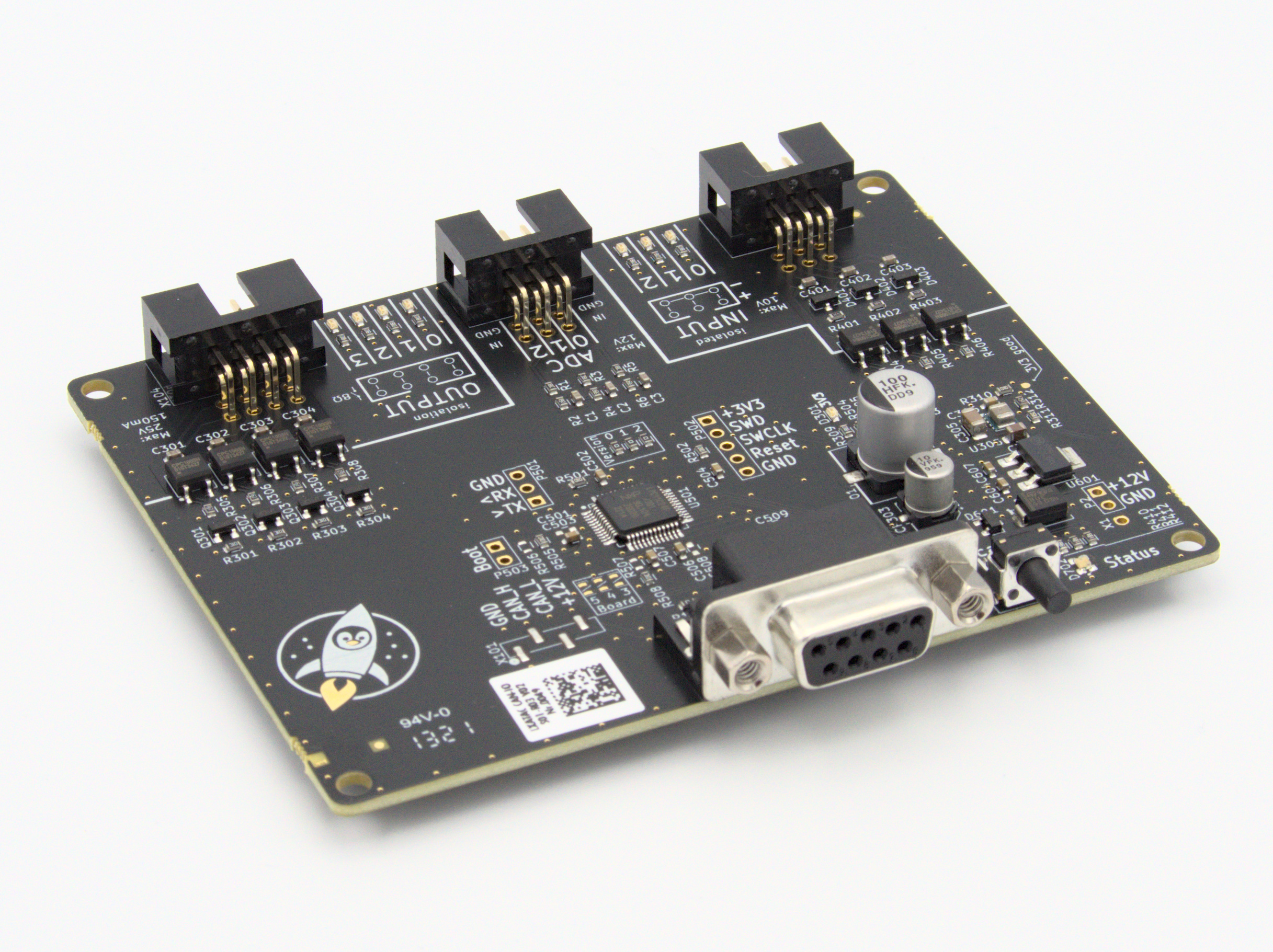
LXA IOBus 4DO-3DI-3AI assembled
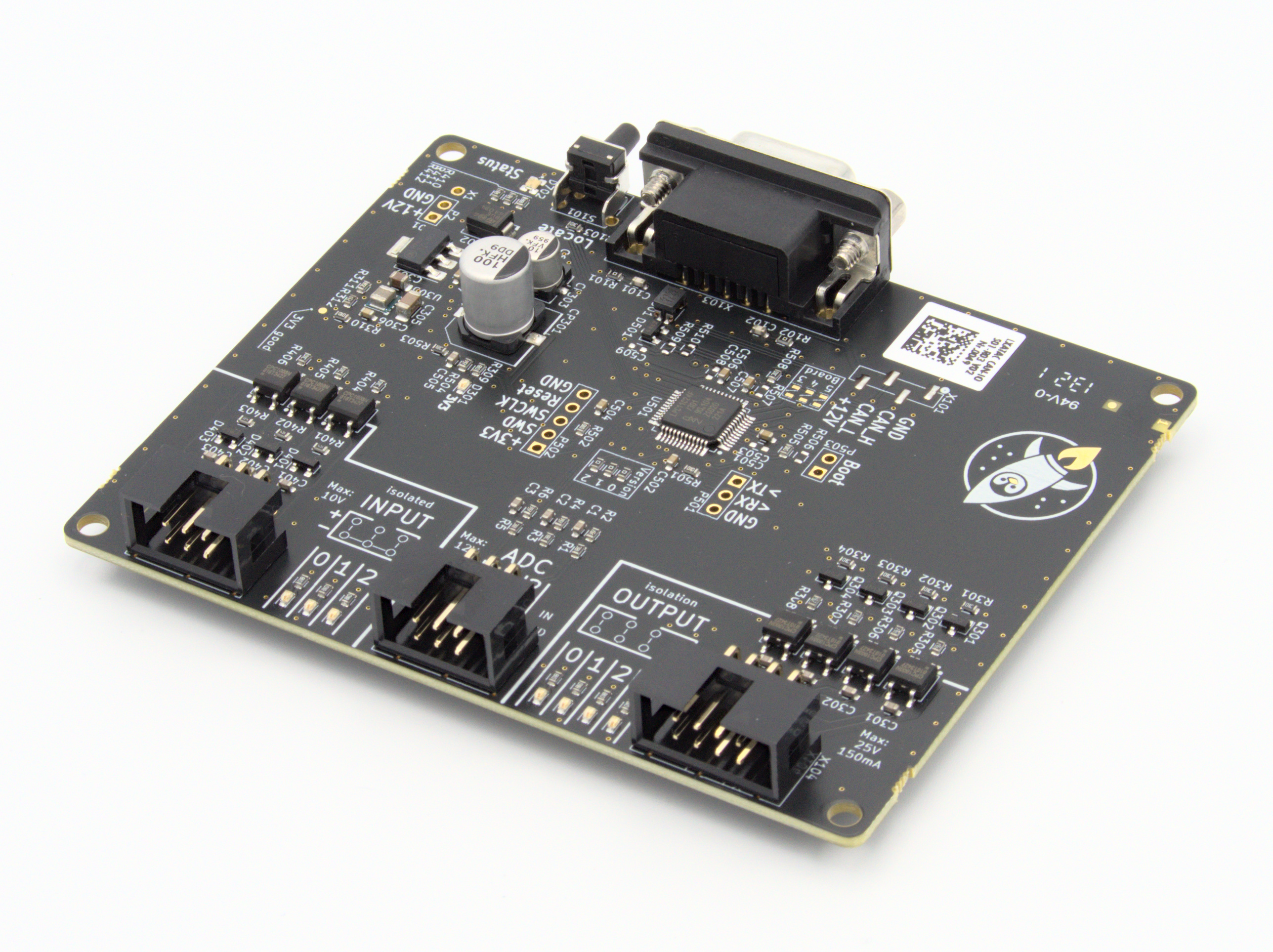
LXA IOBus 4DO-3DI-3AI assembled
Our Commitment to Quality
This device is manufactured in Germany. Each device is put into operation and tested by hand by Linux Automation.
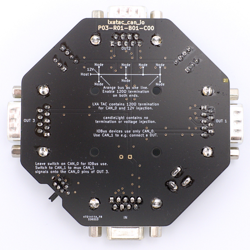
Multi-Plug 1BI-3BO
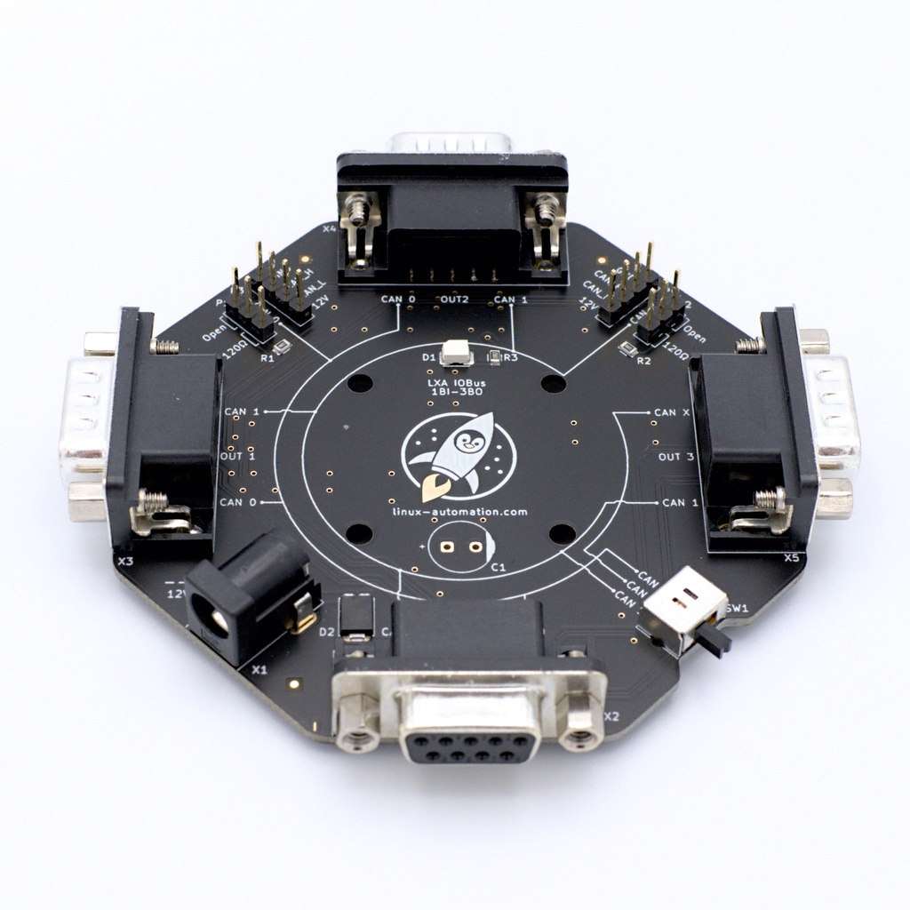
With the voltage injector, several IOBus devices can be supplied with 12V. For this purpose, the 1BI-3BO is plugged between the CAN adapter and the IOBus devices.
The data lines of both CAN buses are connected. The 1BI-3BO contains terminating resistors for both CAN buses.
Scope of Delivery:
- 1BI-3BO Assembly (fully assembled)
- Power Supply Unit: 12 V, 1.5 A (Euro-plug CEE7/16)
- D-Sub 9-pin Cable for connection of an IOBus device

Ressourcen
| Shop: | https://shop.linux-automation.com/Testautomatisierung/lxa_iobus_1BI-3BO |
| Assembly data: | Schematic, Interactive Placement |
Power-Injector 1BI-1BO
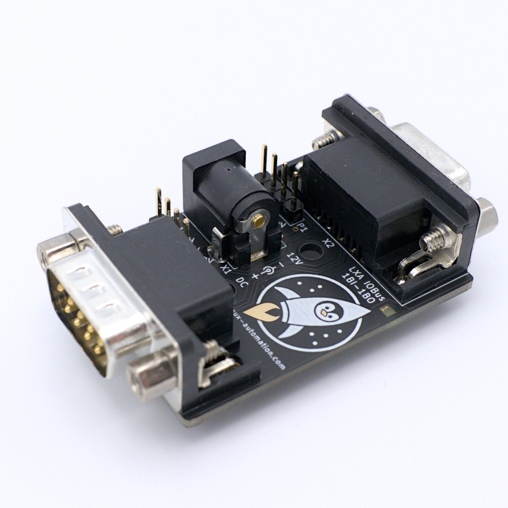
The voltage injector can be used to supply an IOBus device with 12V. The 1BI-1BO is plugged between the CAN adapter and the IOBus device. With a downstream 1BI-3BO or a self-built distributor, several IOBus devices can be operated.
The data lines of both CAN buses are connected. The 1BI-1BO contains a terminating resistor for the first first bus.
Scope of Delivery:
- 1BI-1BO Assembly (fully assembled)
- Power Supply Unit: 12 V, 1.5 A (Euro-plug CEE7/16)
- D-Sub 9-pin Cable for connection of an IOBus device
Ressourcen
| Shop: | https://shop.linux-automation.com/Testautomatisierung/lxa_iobus_1BI-1BO |
| Assembly data: | Schematic, Interactive Placement |