Operation
Software
Note
Make sure you have installed the control software as described in Software Commissioning.
This chapter should give you a general overview of the lxa-iobus-server
software and how it may be integrated into your workflows.
A more in-depth documentation is provided in the lxa-iobus-server
handbook.
The lxa-iobus-server provides a gateway between the CAN-based
IOBus communication protocol for use with lab devices and a
HTTP REST-based protocol for communication with test-automation software.
Running the Server
For basic operation the lxa-iobus-server can be started from
the command line, supplying the name of a CAN interface as the
only parameter:
$ lxa-iobus-server can0
starting server on http://localhost:8080/
Web Interface Usage
Once started the server should start enumerating devices connected to the bus. Visit the iobus-server web interface at http://localhost:8080/ for a list of detected IOBus devices:
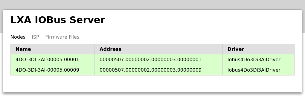
List of nodes in the IOBus Server webinterface
More options to control a particular node are available by clicking on a line in the list:
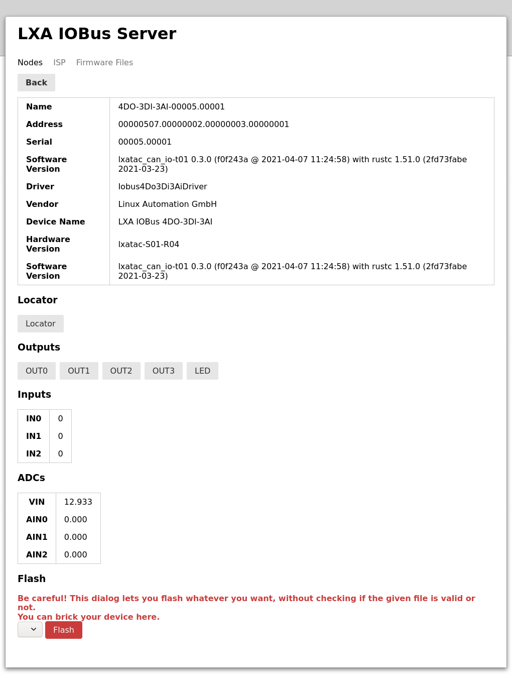
The IOBus Server node control interface
Click on the corresponding button to toggle the status of an output.
Toggling the Locator LED, that can be used to find a particular device in a lab, is done by clicking the Locator button in the interface. The Locator indicator can also be used in the opposite direction, as pushing the locator button on the LXA IOBus 4DO-3DI-3AI also toggles the state of the on-board LED and the one shown in the web interface:
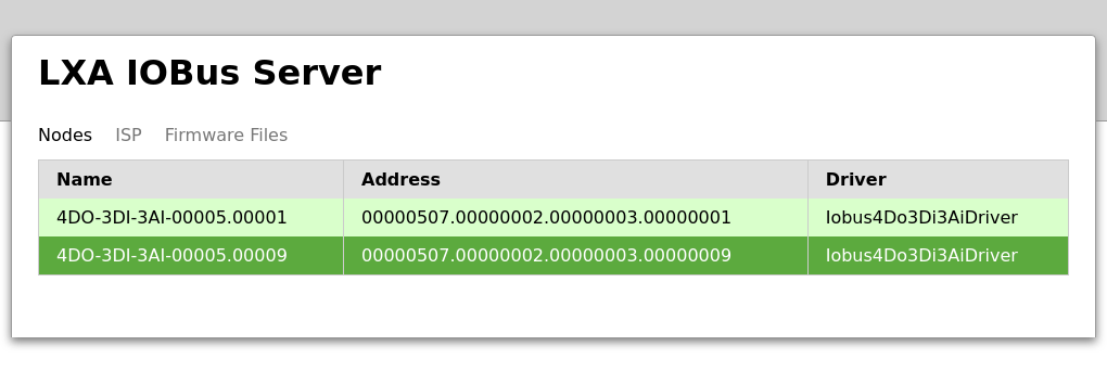
List of nodes. Device “00005.00009” has an active Locator.
REST Interface Usage
The actions available through the web interface can alternatively be performed programmatically using the REST API provided by the server:
# Get a list of available nodes:
$ curl http://localhost:8080/nodes/
{"code": 0, "error_message": "", "result": ["4DO-3DI-3AI-00005.00009", "4DO-3DI-3AI-00005.00001"]}

# Get a list of pins on a device:
$ curl http://localhost:8080/nodes/4DO-3DI-3AI-00005.00001/pins/
{"code": 0, "error_message": "", "result": ["OUT0", "OUT1", "OUT2", "OUT3", "LED",
"IN0", "IN1", "IN2", "VIN", "AIN0", "AIN1", "AIN2"]}

# Get the current status of a pin:
$ curl http://localhost:8080/nodes/4DO-3DI-3AI-00005.00001/pins/IN0/
{"code": 0, "error_message": "", "result": 0}

# Set the status of a pin:
$ curl -d "value=1" -X POST http://localhost:8080/nodes/4DO-3DI-3AI-00005.00001/pins/OUT1/
{"code": 0, "error_message": "", "result": null}

# Toggle the Locator LED:
$ curl -X POST http://localhost:8080/nodes/4DO-3DI-3AI-00005.00001/toggle-locator/
{"code": 0, "error_message": "", "result": null}
Tool Integration
The labgrid project has support for the LXA IOBus 4DO-3DI-3AI. An output pin of the device shown above can be exposed as a labgrid resource using a piece of configuration like this:
LXAIOBusPIO:
  host: localhost:8080
  node: 4DO-3DI-3AI-00005.00001
  pin: OUT0
  invert: False
See labgrid’s documentation for more details.
Direct IOBus Protocol Interaction
The lxa-iobus-server, as described above, is the preferred method of
communication with IOBus nodes.
An alternative means of communication is by directly sending bare
CAN packets on the bus.
This can, for example, be achieved using the cansend command,
that may be installed using sudo apt install can-utils on a
Debian based Linux distribution.
Warning
The IOBus protocol, as demonstrated below, is not a stable API. You may need to adapt custom protocol implementations to stay compatible with new firmware releases.
# Configure the CAN-Interface bitrate
$ sudo ip link set can0 type can bitrate 100000

# Set the interface to the "up" state
$ sudo ip link set can0 up

# Set all devices on the bus to the configuration mode
$ cansend can0 "7e5#0401000000000000"
#                     ^^------------- Mode              1 (Configuration)
#                   ^^--------------- Command           4 (Switch mode global)
#               ^^^------------------ CAN Message ID 2021

# Configure a node id for the IOBus device
$ cansend can0 "7e5#1101000000000000"
#                     ^^------------- New node ID       1
#                   ^^--------------- Command          17 (Configure node ID)
#               ^^^------------------ CAN Message ID 2021

# Set all devices on the bus to the operation mode
$ cansend can0 "7e5#0400000000000000"
#                     ^^------------- Mode              0 (Operation)
#                   ^^--------------- Command           4 (Switch mode global)
#               ^^^------------------ CAN Message ID 2021

# Deactivate the IOBus watchdog
# (If the watchdog is active the node will reset it's node ID when
# it is not addressed (e.g. read a value) once every 30 seconds.)
$ cansend can0 "601#23062d0100000000"
#                           ^^^^^^^^- Value                     0 (0: Deactivate, 1: Activate)
#                         ^^--------- Sub Index                 1
#                     ^^^^----------- Index                0x2d06
#                   ^^--------------- Command/Length/Type³   0x23
#               ^^^------------------ CAN ID⁴               0x601

# Activate the LXA IOBus 4DO-3DI-3AI Output 0
$ cansend can0 "601#230021020100ffff"
#                               ^^^^- Output mask¹         0xffff
#                           ^^^^----- Output state²        0x0001
#                         ^^--------- Sub Index                 2
#                     ^^^^----------- Index                0x2100
#                   ^^--------------- Command/Length/Type³   0x23
#               ^^^------------------ CAN ID⁴               0x601
#
# ¹: 0xffff = 0b1111111111111111
#               ^^^^^^^^^^^^^^^^----- Output 0-15 Are written
#
# ²: 0x0001 = 0b0000000000000001
#                              ^----- Output    0 High
#               ^^^^^^^^^^^^^^^------ Output 1-15 Low (Ignored due to masking)
#
# ³: 0x23 = 0b00100011
#                   ^^--------------- Type    3
#                ^^^----------------- Length  0 (4 - LENGTH_BYTES)
#             ^^^-------------------- Command 1
#
# ⁴: 0x601 =     0x600 |     0x001
#          = BASE_ADDR | NODE_ADDR

# Deactivate all LXA IOBus 4DO-3DI-3AI Outputs
$ cansend can0 "601#230021020000ffff"
#                               ^^^^- Output mask          0xffff
#                           ^^^^----- Output state⁵        0x0000
#                         ^^--------- Sub Index                 2
#                     ^^^^----------- Index                0x2100
#                   ^^--------------- Command/Length/Type    0x23
#               ^^^------------------ CAN ID                0x601
#
# ⁵: 0x0000 = 0b0000000000000000
#                              ^----- Output    1 Low
#               ^^^^^^^^^^^^^^^------ Output 2-16 Low  (Ignored due to masking)

# To read back information from the device run candump in the background
$ candump can0 &

# Trigger a readout of the digital input states (the output is generated
# by candump and contains the request, as well as the response)
$ cansend can0 "601#4001210200000000"
  can0  601   [8]  40 01 21 02 00 00 00 00
  can0  581   [8]  53 01 21 02 00 00 00 00
#                              ^^-^^-^^-^^- Input states⁶ 0x00000000
#                           ^^------------- Sub Index              2
#                     ^^-^^---------------- Index             0x2101
#                  ^^---------------------- C/L/T (request)     0x40
#                  ^^---------------------- C/L/T (response)    0x53
#       ^^^-------------------------------- CAN ID (request)   0x601
#       ^^^-------------------------------- CAN ID (response)⁷ 0x581
#
# ⁶: 0x00000000 = 0b00000000000000000000000000000000
#                                                  ^----- Input    0 Low
#                   ^^^^^^^^^^^^^^^^^^^^^^^^^^^^^^^------ Input 1-31 Low
# ⁷: 0x581 =     0x580 |     0x001
#          = BASE_ADDR | NODE_ADDR

# Trigger a readout of an anlog input (the output is generated
# by candump and contains the request, as well as the response)
$ cansend can0 "601#40DC2A0400000000"
  can0  601   [8]  40 DC 2A 04 00 00 00 00
  can0  581   [8]  4B DC 2A 04 FF 03 00 00
#                              ^^-^^------- ADC Value         0x03ff
#                           ^^------------- Sub Index⁸             4
#                     ^^-^^---------------- Index             0x2adc
#                  ^^---------------------- C/L/T (request)     0x40
#                  ^^---------------------- C/L/T (response)    0x4B
#       ^^^-------------------------------- CAN ID (request)   0x601
#       ^^^-------------------------------- CAN ID (response)  0x581
#
# ⁸: 4 = (          0 + 1) * 4
#      = (ADC_CHAN_ID + 1) * 4
Warning
The commands above assume a single node on the bus, as the first two CAN packets would otherwise configure all nodes on the bus to share a single node id. A configuration of multiple nodes may be performed using LSS Fastscan.