Hardware Features
The LXA TAC provides external interfaces on three of the six sides of the case. These three sides are:
The Infrastructure/Lab side
Used to power the TAC, provide a communication uplink, debugging access and a display.
The DUT side
Used to connect the device under test and DUT-related accessories.
The Top side
Provides blinking lights and descriptions for the interfaces on the other sides.
Lab Side
This side of the TAC will mostly be connected to your infrastructure, e.g. a PoE switch in a rack or a normal switch and a power supply.
From left to right: Display, Upper and Lower Button, USB Gadget port, 12V input and Ethernet Uplink.
Display and Buttons
The display and buttons are used to interactively control the TAC, e.g. while first setting up a DUT or debugging the setup. The behaviour of the buttons changes from screen to screen, but as a general pattern short presses mean “navigate through a menu” and long presses mean “perform an action”.
USB Gadget Port
The USB Gadget port can be used to provide various USB device features to a DUT or a host computer (see USB Gadget: tac-gadget-* for examples of available gadget functions). It can also be used to deploy new software to the LXA TAC itself via the SoC’s bootrom, making the device practically unbrickable.
12V Input
The TAC can be powered via either the PoE-capable Uplink port or the 12V barrel jack input. Any voltage-regulated 12V supply capable of delivering 1.5A or more with a center-positive barrel jack connector should be able to power the TAC.
Uplink Port
The Uplink port can be used to supply the TAC with power via power over ethernet (802.3af up to 13W) and to provide network access to the TAC.
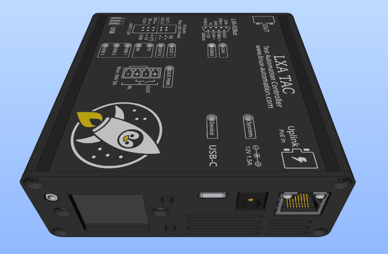
DUT Side
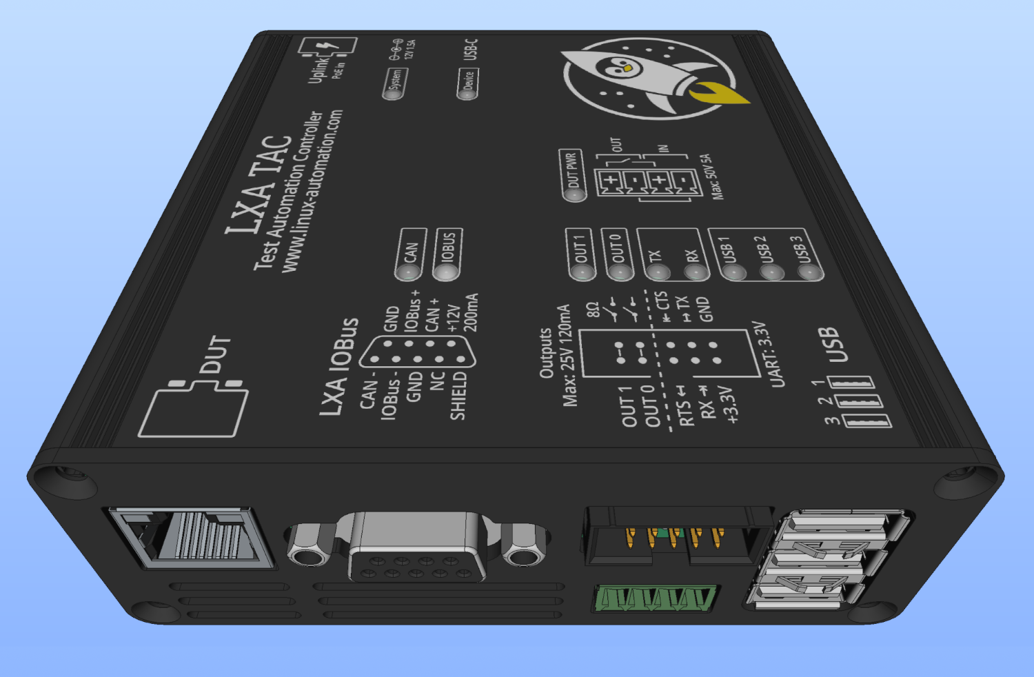
From left to right: DUT Ethernet Port, LXA IOBus/CAN port, Outputs and DUT UART (top), Switchable DUT Power Supply (bottom), USB Host.
DUT Ethernet Port
The DUT ethernet port provides a gigabit ethernet connection for use with your device under test. The Uplink and DUT ports are connected to a gigabit ethernet switch inside the TAC, allowing data to flow between them at line speed without producing any load on the main processor.
The behaviour of the two ports is re-configurable in software to e.g. allow isolating the networks on the two ports from each other, untagging a VLAN to the DUT port or even performing routing / using a VPN.
Configuration is done using DSA. So both switch ports are represented as normal network interfaces in Linux.
You should keep in mind that layer 3 and higher features, like using the TAC as a router, involve the main processor and will not operate at full gigabit speed.
LXA IOBus/CAN port
The IOBus port provides two CAN FD capable CAN interfaces and a 12V 200mA power supply. The first CAN interface is intended for use with the LXA IOBus line of products. The pinout matches that of other LXA IOBus devices, making it possible to directly connect them to the TAC. The TAC also contains a pre-installed termination resistor on the first CAN interface to make the IOBus experience fully plug and play.
The second CAN interface can be used to e.g. connect to a CAN bus on your device under test. This port contains a switchable 120Ω termination resistor that can be enabled in software.
Both CAN channels are represented as SocketCAN devices.
Outputs OUT 0/OUT 1
The LXA TAC provides two outputs that can be used to e.g. assert a
~RESETline on you DUT, select an alternative bootmode by pulling a pin toGND/VCCor simulate button presses by connecting the two pins of a button.The outputs behave a bit like buttons/switches, in that they provide two connections each which are normally not electrically connected but can be shorted together on demand instead of providing a specific voltage level.
The LXA TAC outputs are able to read back the voltage between the output pins. This can e.g. be used to measure the
VCCof your DUT, which is often present on a~RESETline while it is not asserted.Note
The OUT 0 / OUT 1 pins are allowed to float in voltage from the TAC’s
GND. It is your responsibility to make sure that they stay within about ±25V ofGND.The outputs are not intended to switch large loads and are not guaranteed to work at frequencies above a few Hz.
The implementation of the voltage feedback measurement results in the outputs being pulled towards
GNDwith about a resistance of about 1MΩ even when open. This may cause issues with very high impedance pull-up-resistors on DUTs.
DUT UART
Located on the same box connector as the outputs is 3.3V logic-level UART with optional hardware flow control that can be connected to the serial console of your device under test.
The UART allows baud rates of up to 4,000,000 Baud.
Some DUT fail to power-cycle successfully when connected to conventional USB to UART converters, due to leakage currents from the
TXpin and pull-up-resistors on theRXpins keeping parts of the chip active. To mitigate these effects the UART pins on the LXA TAC can be set to a floating state by software. It is also possible to disable theRXandTXpaths separately from one another to enable e.g. a receive-only mode until a “OK” message is received.Linux Automation GmbH provides adapters to convert the 3.3V logic level to 1.8V and 2.5V logic level UARTs as well as adapters to classic RS-232. These adapters may put additional restrictions on the baud rate and current leakage into the DUT.
Note
RTS (Request to Send) and CTS (Clear to Send) pins are commonly used as low-cost GPIOs, but they cannot be used for this purpose on the LXA TAC. This is due to an internal limitation of the UART in the STM32 microcontroller. These pins can only be used for hardware flow control.
Attempting to read or write values to RTS or CTS using libraries like
pyserialwill not work and may even fail silently.As an alternative, consider using pins
OUT 0andOUT 1, which can serve a similar function.
DUT Power
The LXA TAC contains a power switch capable of switching non-inductive loads up to 50V at 5A.
The power switch can be connected between the normal power supply of your DUT and the DUT itself. This enables the TAC to power-cycle the DUT, measure the supply voltage and the current consumption.
The pins of the power switch are electrically isolated from the power supply of the TAC, allowing them to safely float by a few volts with respect to the TAC’s reference voltage. Please contact Linux Automation GmbH for confirmation if you need more than a couple of volts of isolation.
On power-off the output side of the power switch can either be discharged by a LXA TAC internal 47kΩ resistor or be left floating completely.
USB Host
The three external USB-A ports of the TAC are connected to an on-board USB Hub and can be used to connect devices like the LXA USB-Mux, the LXA USB-SD-Mux, the DUT in gadget mode or other USB peripherals.
To stay within the 13W power limit of the Uplink PoE supply the USB ports are limited to a common maximum current consumption of 700mA. In addition to that the ports are individually limited to a maximum consumption of 500mA each. The System Daemon: tacd provides views of the USB host port currents on its web interface and on the display.
The power supply and data lines of each USB port can be separately turned off or on in software via the System Daemon: tacd web interface/API or the
uhubctlcommand.
Top Side
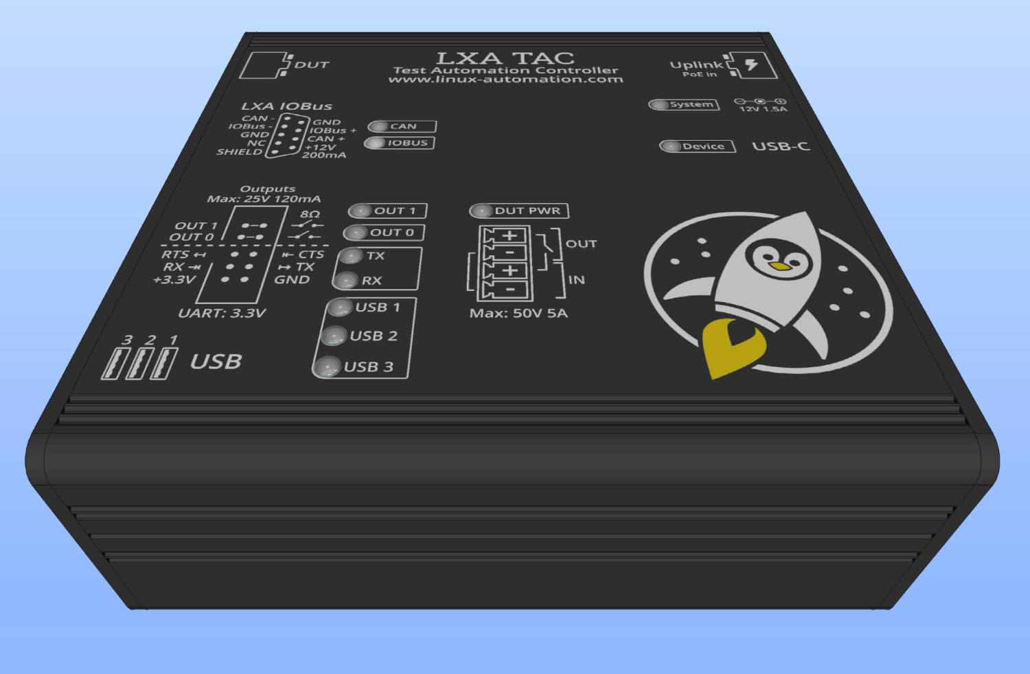
Status LEDs and description text.
The Top side of the TAC provides status information via a collection of LEDs and printed descriptions of the previously mentioned interfaces.